Push Back Block Project
Overview
For this project I will CAD this year's vex game object an 18-sided block. This project can be used for my robot's CAD as it will allow me to visualize how the robot interacts with blocks much easier. But it can also be used to make little gifts that can be given to other teams.
Creating the Block CAD
Attempt 1
For this project we will be utilizing a lot of variables in each dimension in order to make it so that it can be used for both purposes. This will allow us to change one dimension, such that all the other dimensions will change with it preserving its shape.
The method I plan on using to create this block is to create half of the block by first creating the square sides before using various tools such as extrude or lofts to create the rest of the sides. Following that I will mirror the block and add finishing touches.
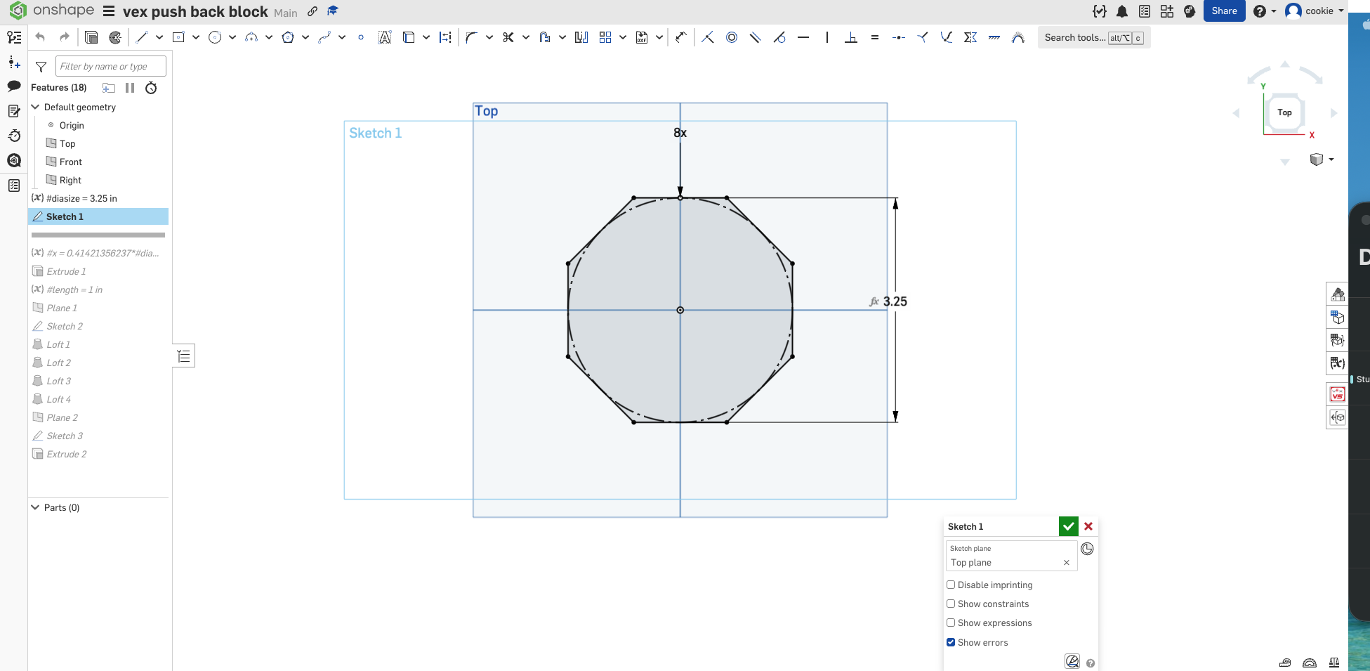
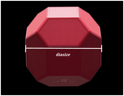
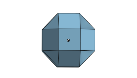
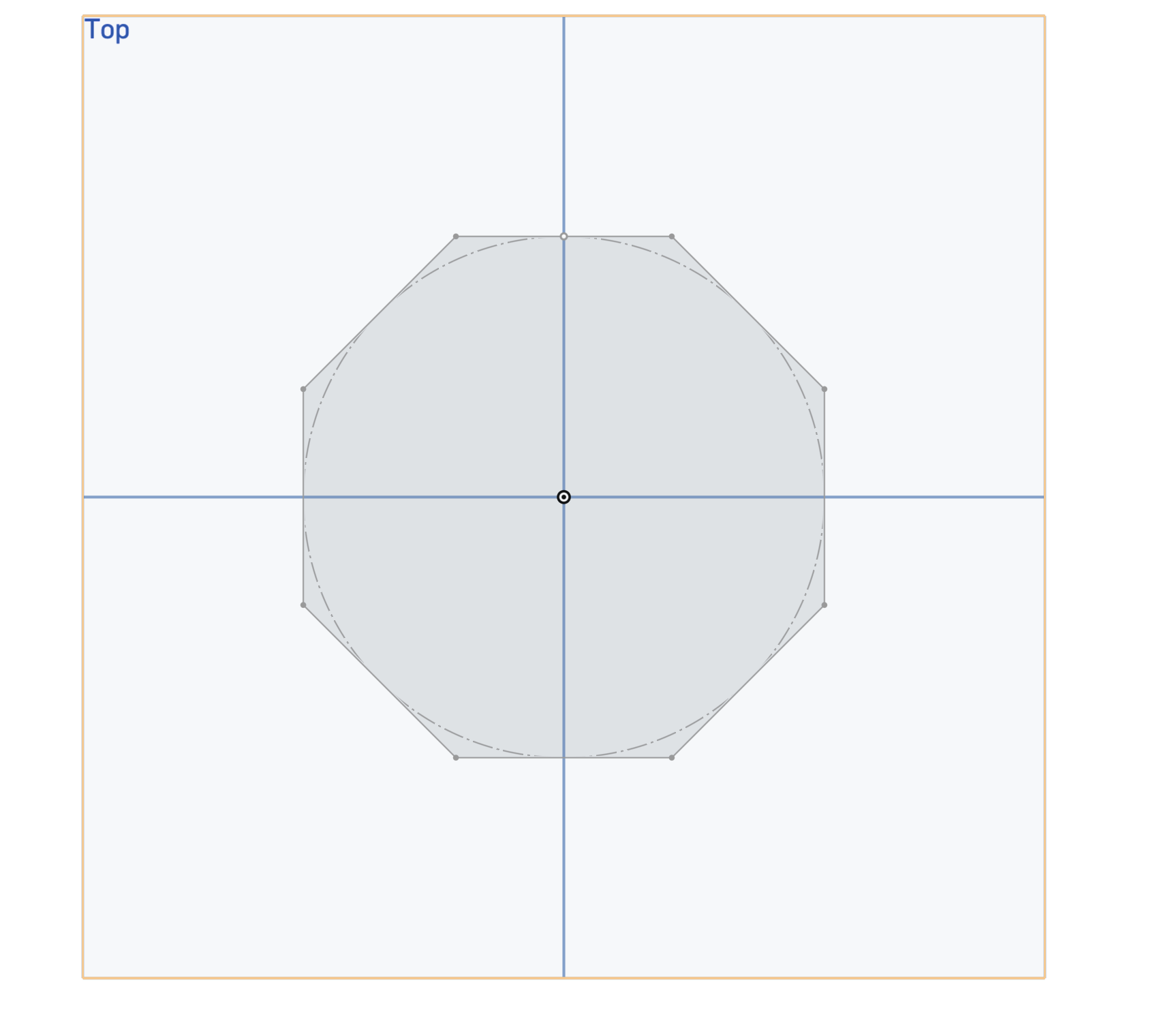
First I started by creating an octagonal shape with the diameter being the variable diasize, which in this case is 3.25".
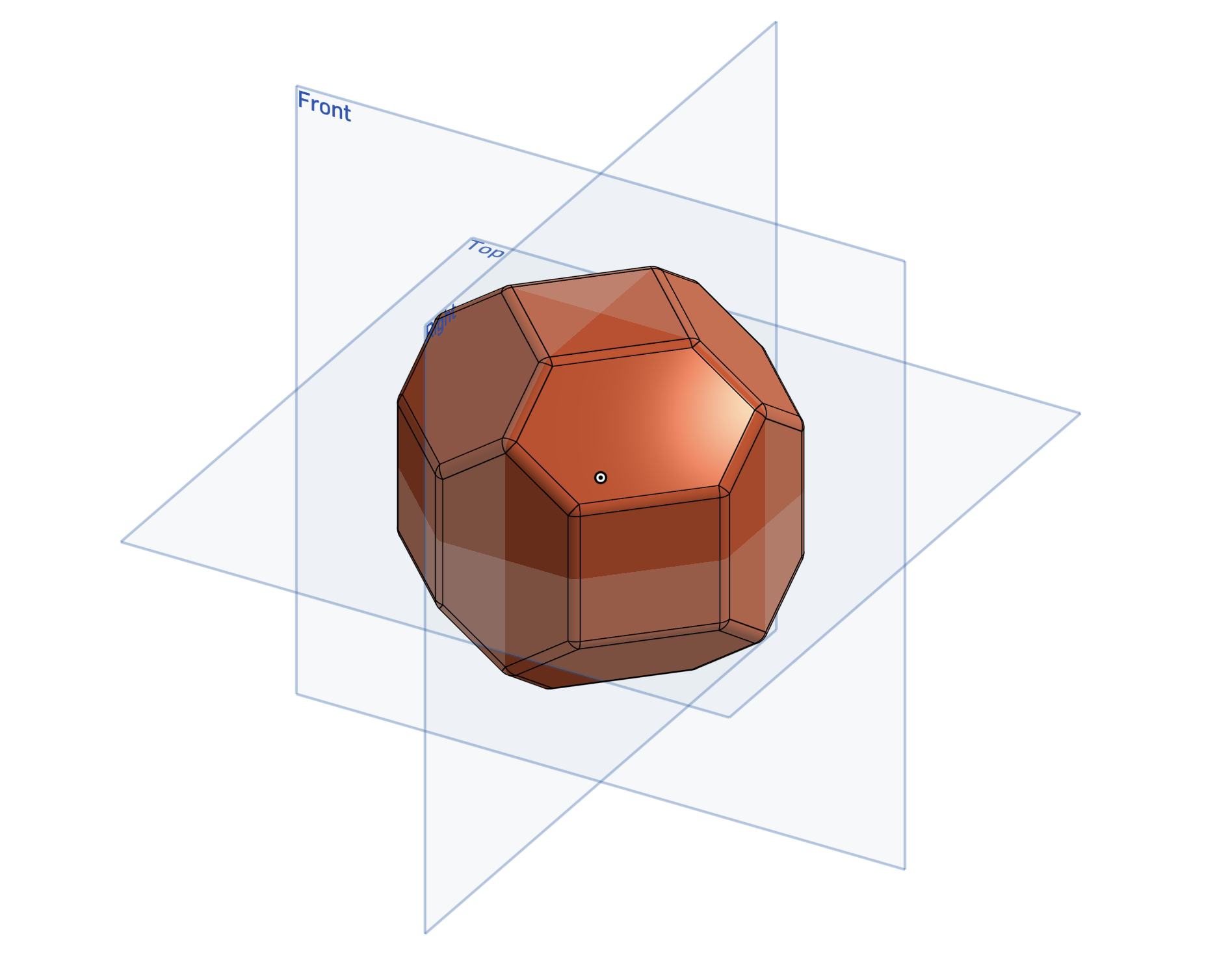
In the final product diasize will look like this:
Next I created a variable table that will allow me to create multiple variables that are related to one another. Here I created the variable x which is the length of the square side of the cube.
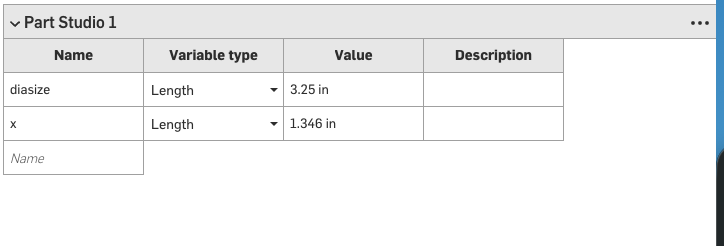
On an octagon(left) and in this finished product (right) x would be:
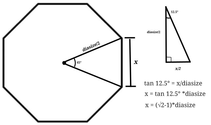
Using trigonometry I am able to calculate that  .
.
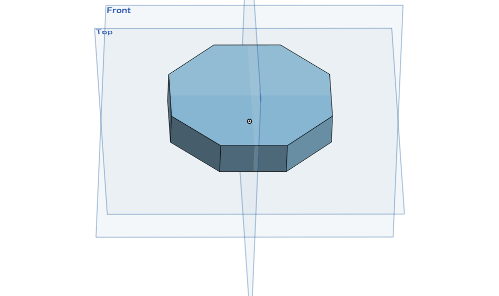
After this I extruded the octagon by half of x making it so that it forms half of the square part of the block.
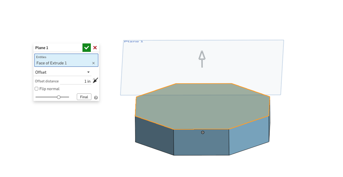
I then created an offset plane diasize inches away from the bottom upside of the extruded octagon (the top plane). On this plane I created a square with a length of x which would become the top square of the cube
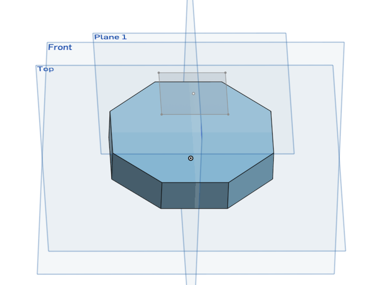
I then used the loft tool to connect one of the edges to the edge of the square, and did this for four of the sides.
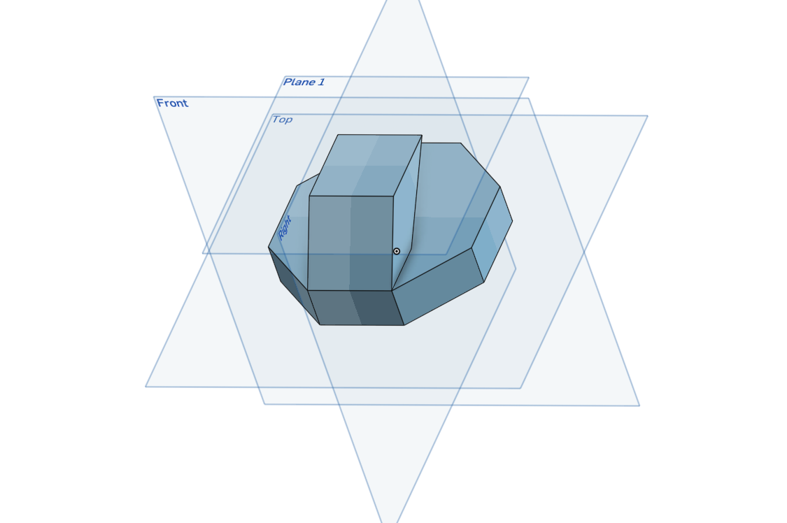
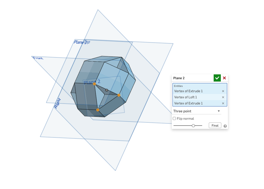
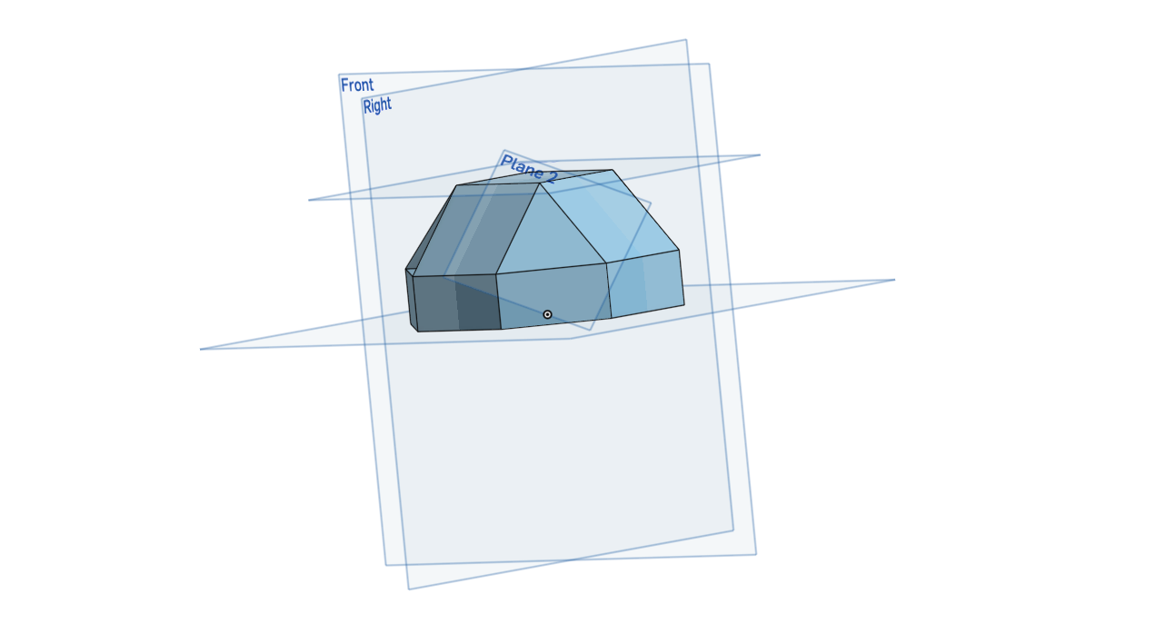
I then used the plane feature and created a plane using three points of the triangle that was formed, before creating a sketch with a triangle and extruding it so that the triangle was filled.
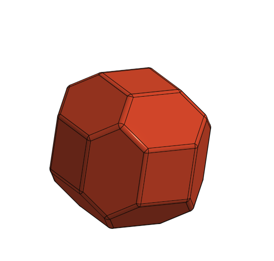
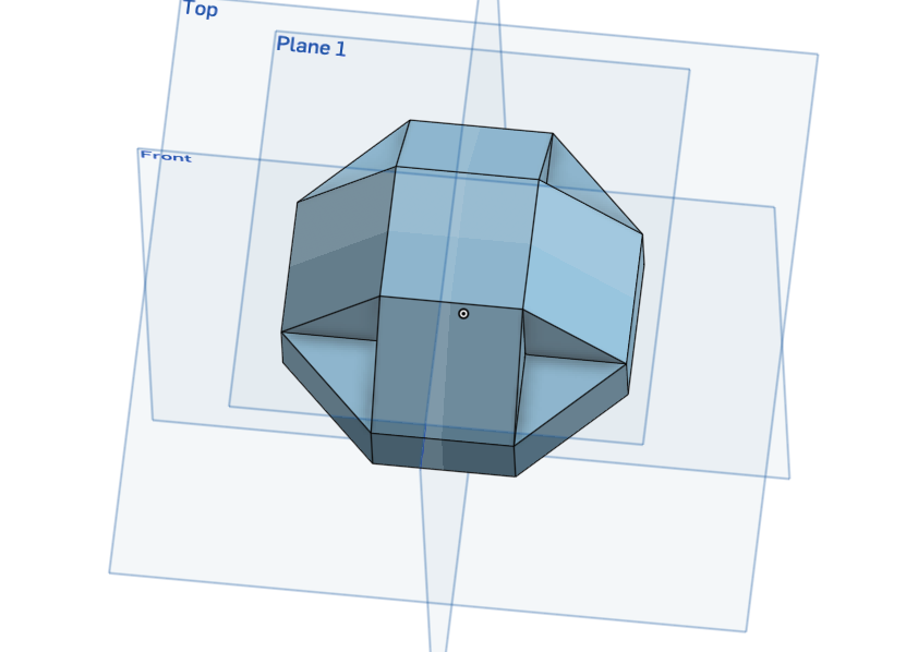
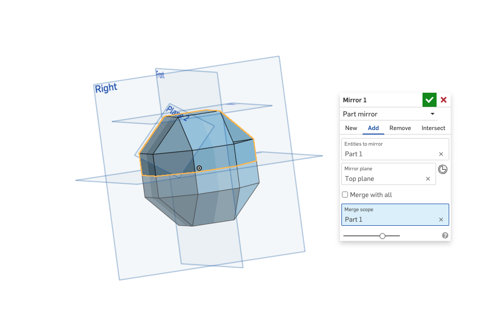
I mirrored the part to get a final block as shown below.
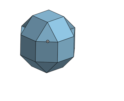
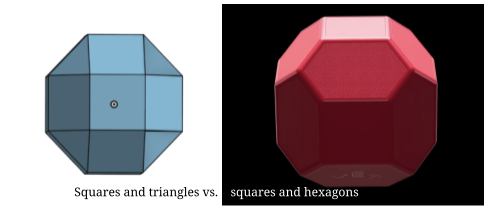
However at this point I realized that the block I had created was composed of squares and triangles, but the block I was trying to create was made of squares and hexagons instead.
Attempt 2
To fix this problem I decided to roll back to the sketch I had made at the very beginning. In the previous attempt of creating the block I had extruded part way and used lofts to create the rest of the sides. However, in this attempt, I planned on creating it by making half of the block as an extruded octagon, and removing part of the sides to create the hexagons and the squares, before once again mirroring the block.
Roll back to the original sketch:
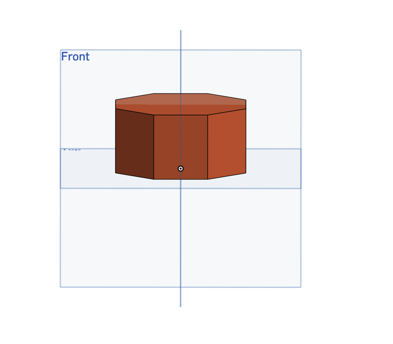
After rolling it back, I extruded the octagon by half of diasize.
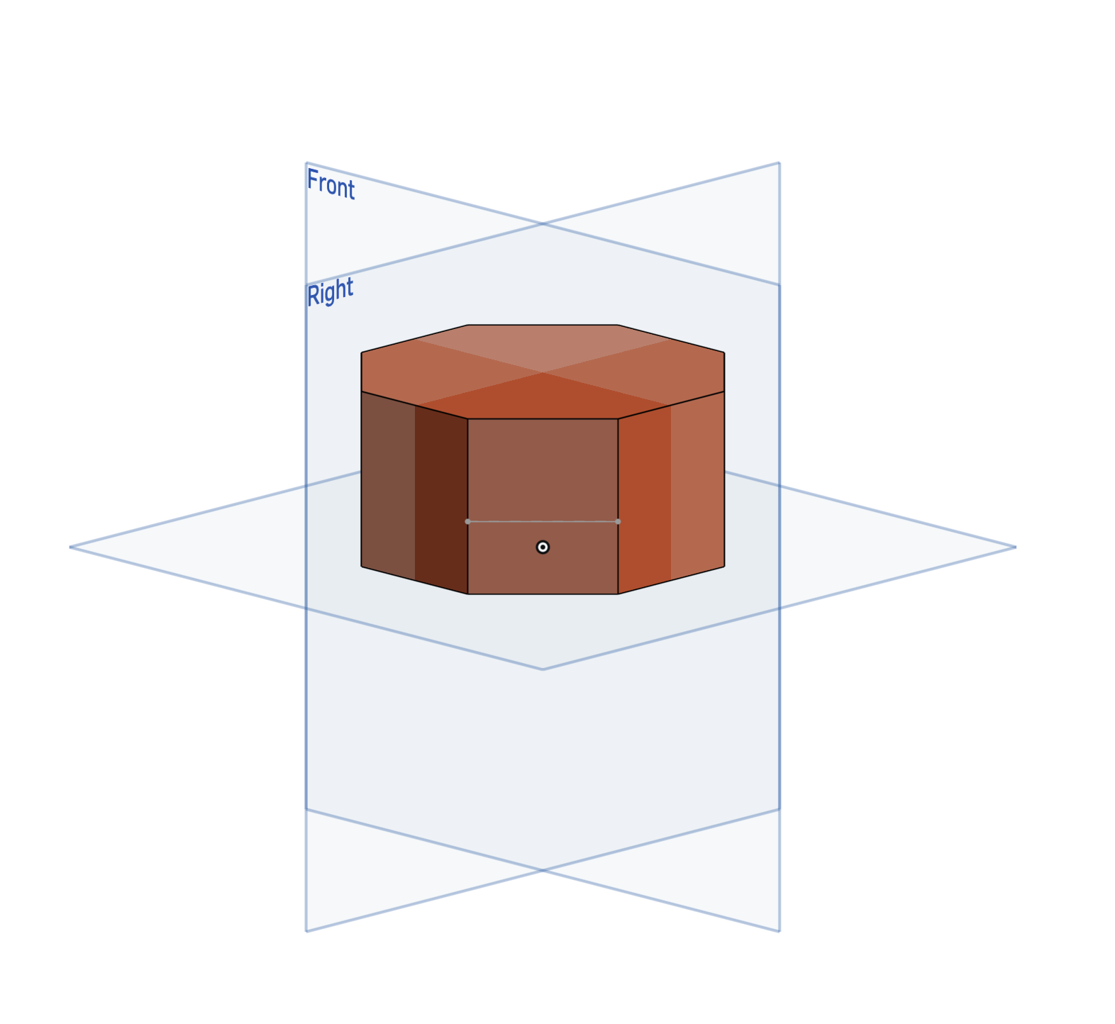
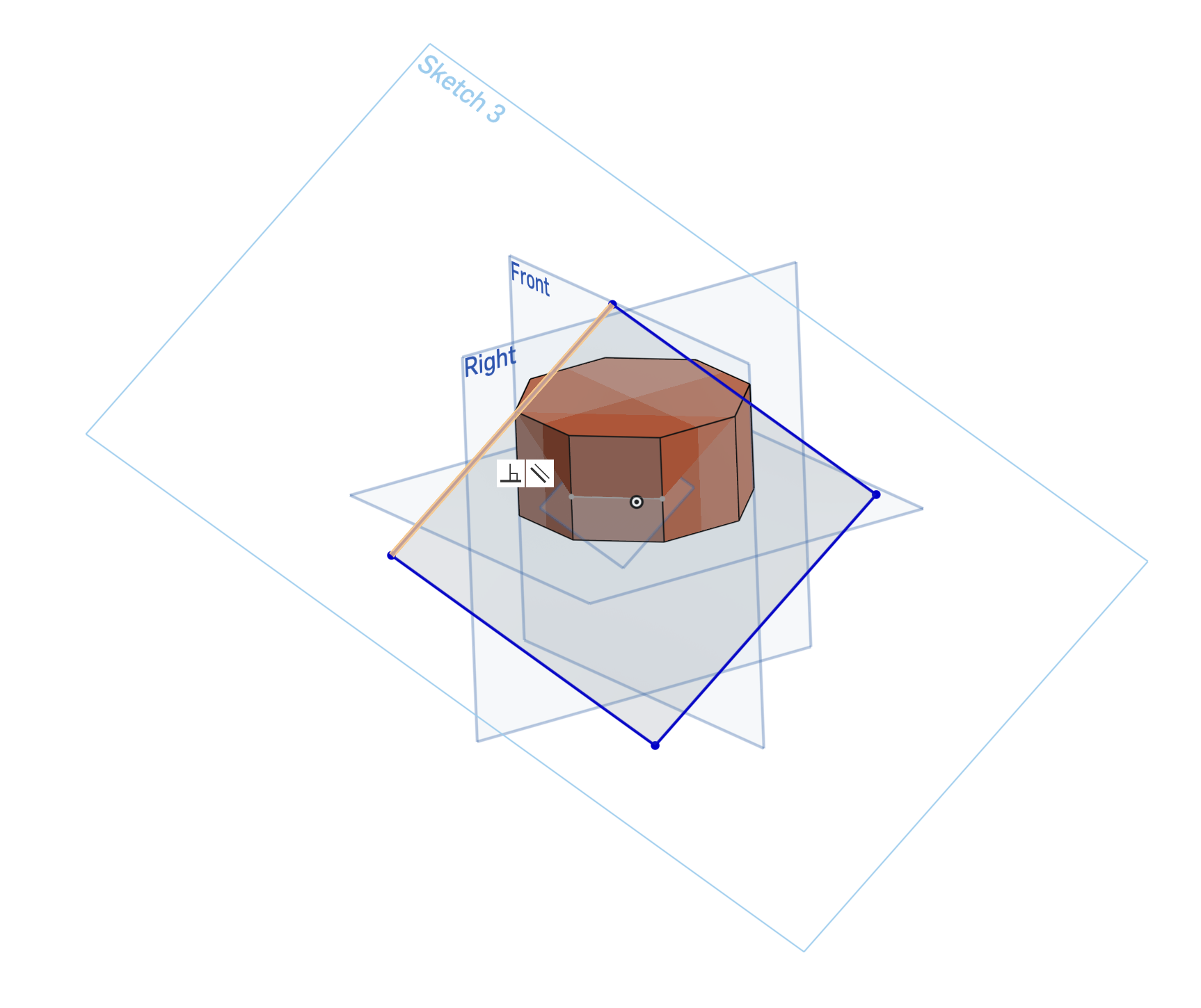
Following this I created a sketch on one of the sides of the octagon, placing a line that is x/2 inches above the top plane. This will mark the edge of where the square will be.
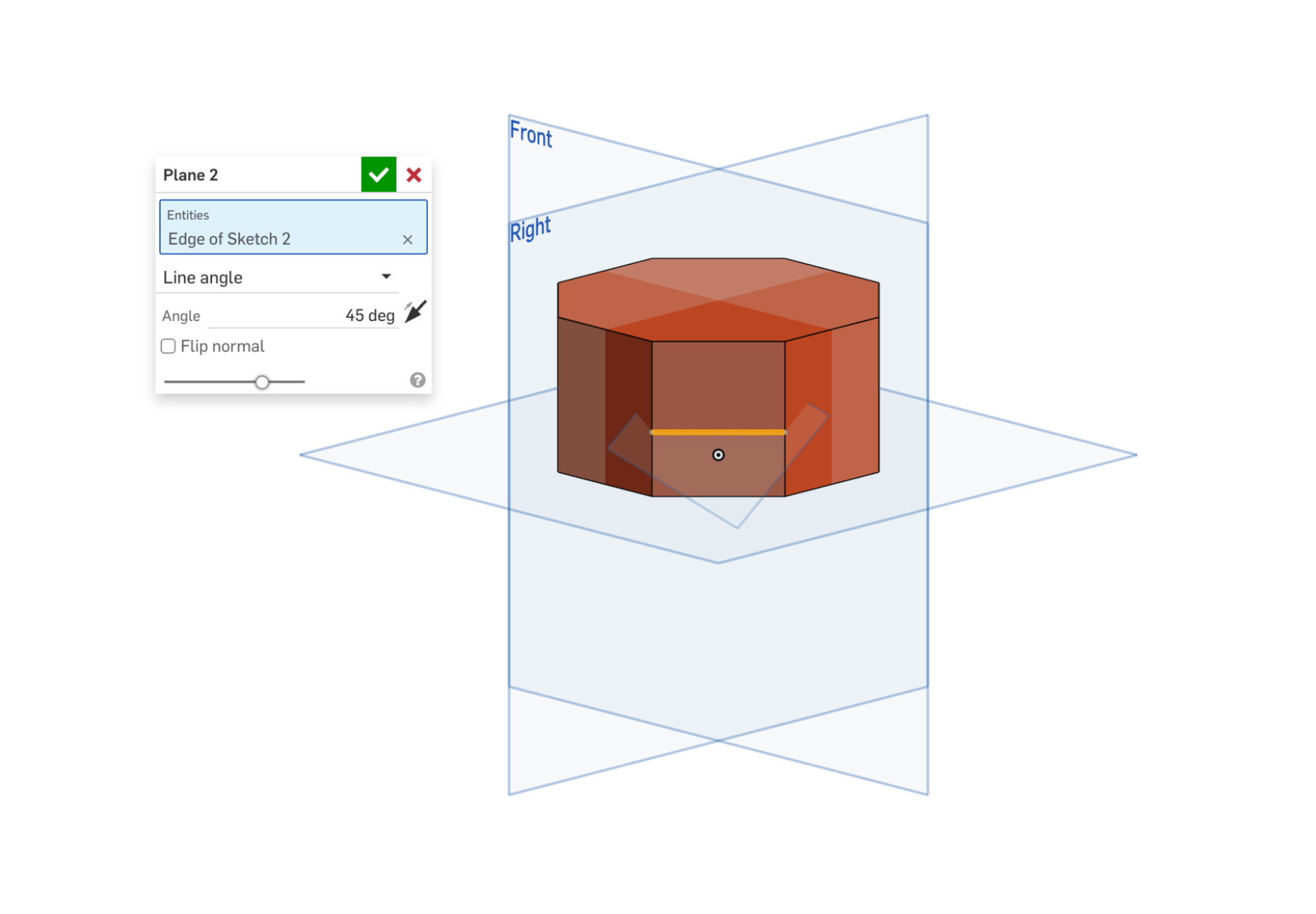
Following this I created a plane on this line with an angle of 45°. I chose this angle because all of the sides of the hexagon should be symmetrical, a property that would only be preserved with a plane of this angle.
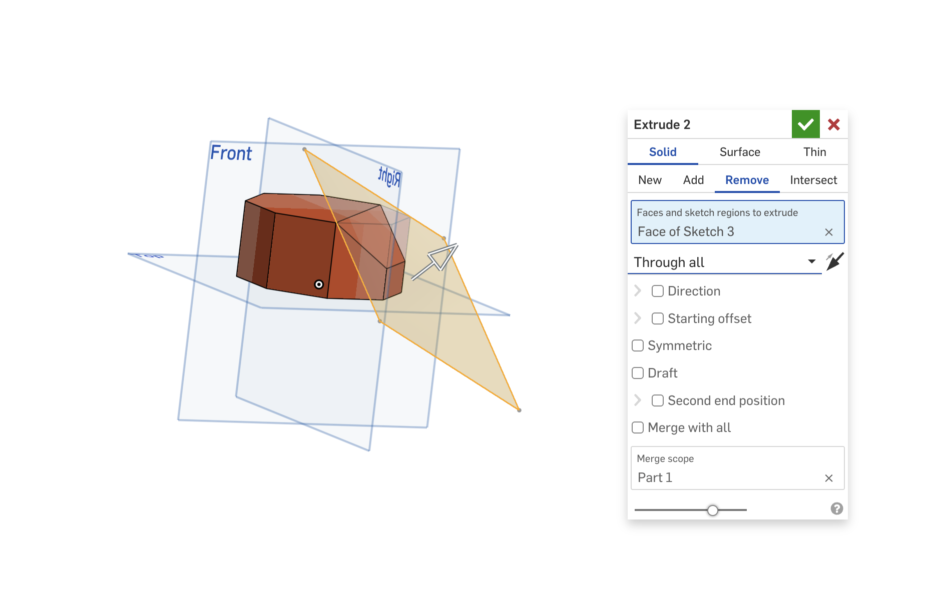
I then created a sketch on this plane with a large rectangle, which would be used to remove part of the edge (using the extrude remove tool). This extrude will form an irregular shape, which once done to all 4 sides will become a hexagon.
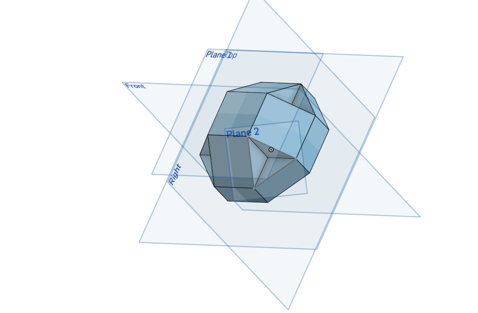
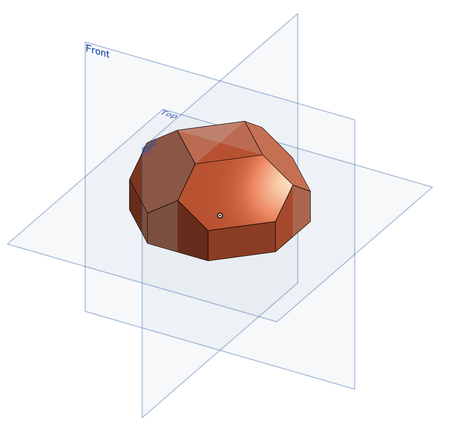
This is the final result once done to all four sides.
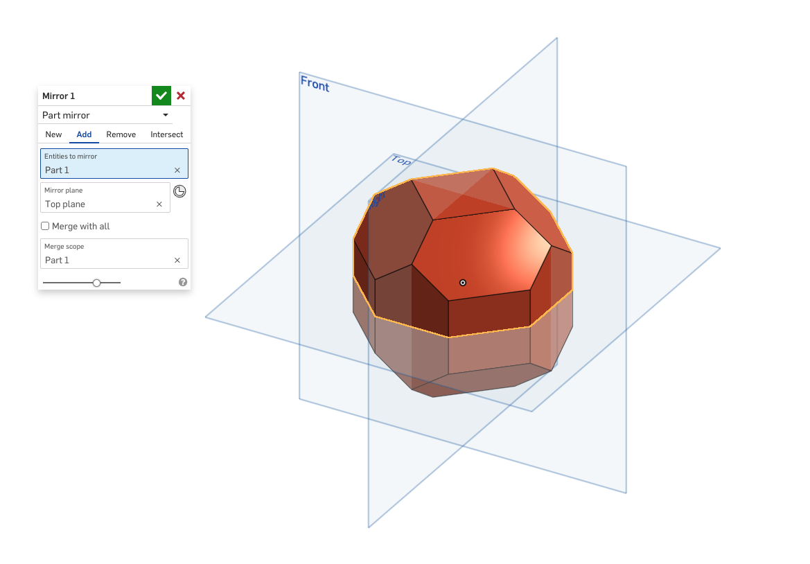
Following this I mirrored this part across the top plane to form the full block.
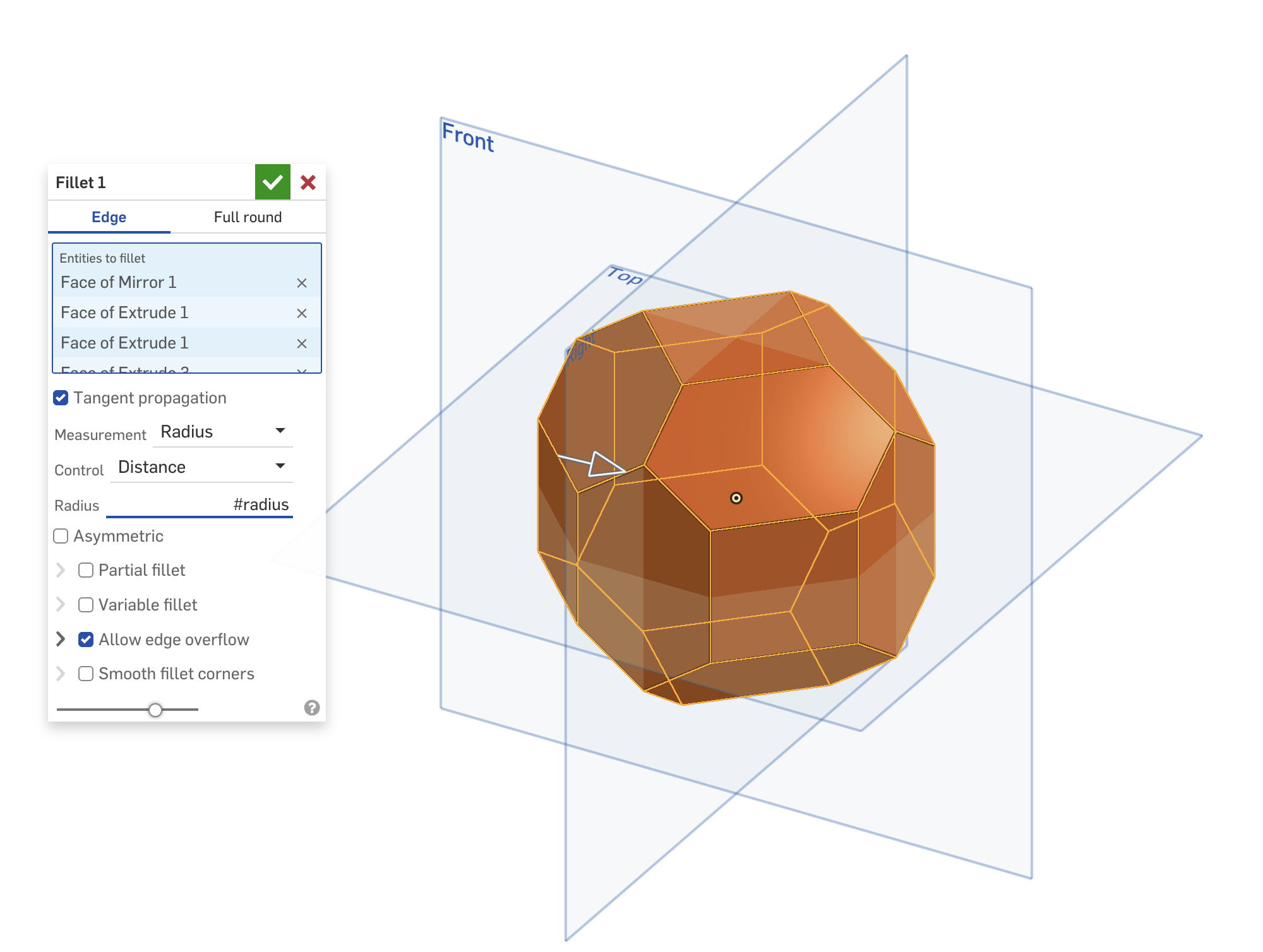
Finally, I added final touches by using the fillet tool on the edges. This tool gives the edges of the block a rounded finish like that of the actual game object. For the fillet radius, I created a new variable radius which is x/10. This variable makes it so that even if the size of the block changes the fillets won't error out, and will preserve its shape.
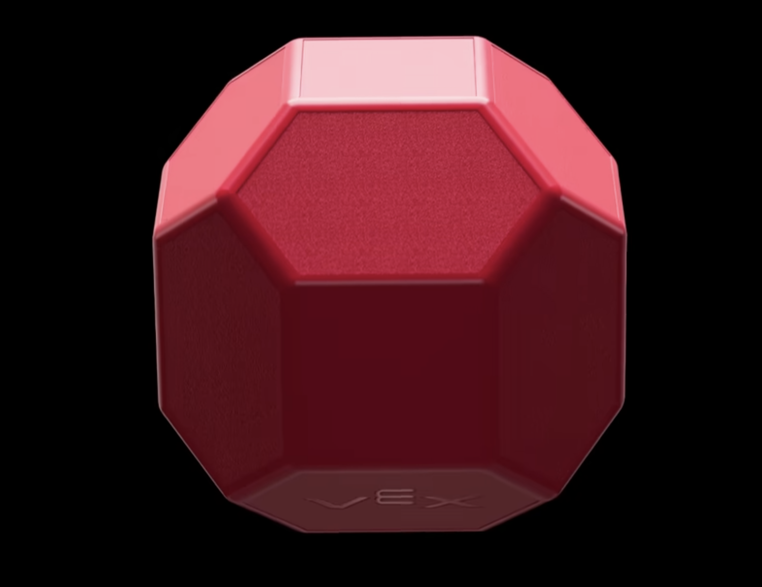
This is the final product of the CAD block: