Hinge Project
Overview
For this project I will CAD and 3D print a hinge. Previously, I have only CADed and 3D printed objects that do not move. However, the hinge is an articulated piece meaning that it is printed so that, once completed, it will be able to move (in this case it should be able to bend at its pin).
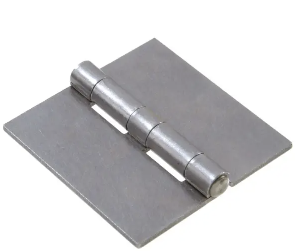
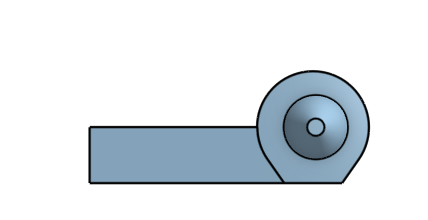
This is an example of how my final model should turn out:
|
|
Attempt 1
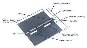
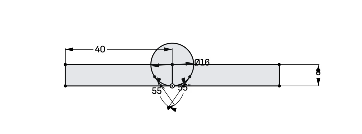
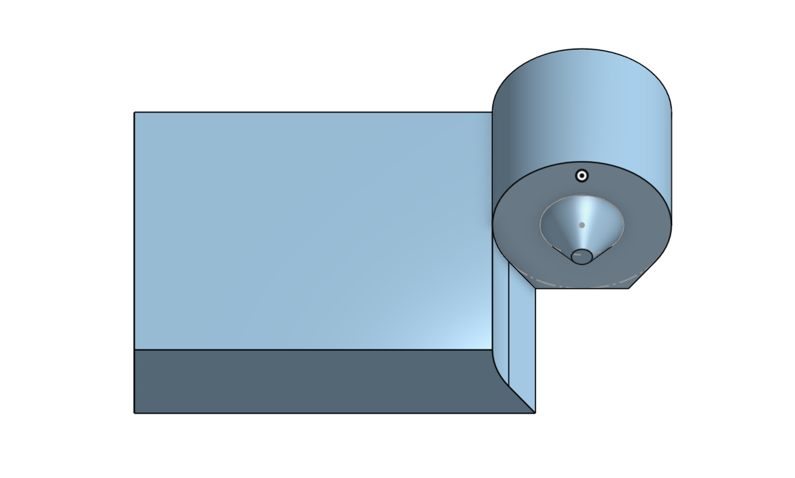
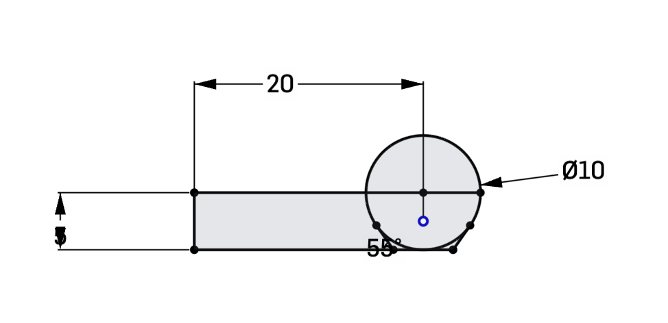
I first started off by creating a sketch that represents the side profile of the hinge. The circle represents the knuckle/barrel (which according to the sketch has a diameter of 16 mm) while the rectangles represent the leaf (which has a width of 40 mm from the center of the barrel and a height of 8 mm).
I then extruded the hinge to make 2 different pieces that would represent different parts of the barrel. On one of the pieces I created a smaller circle, which I extruded with a draft to make a cone-like piece. On the other piece I used the same size circle and used the extrude remove tool to create a gap that would enclose the cone-like extrude of the other piece. These actions created the following piece:
|
|
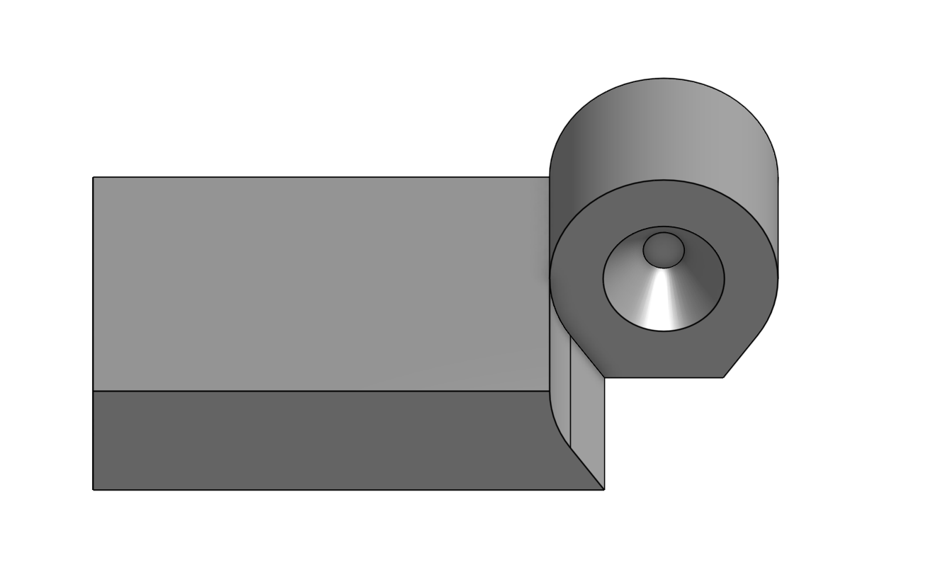
I then mirrored the part making it so that one of the parts enclosed the other, making a longer hinge.
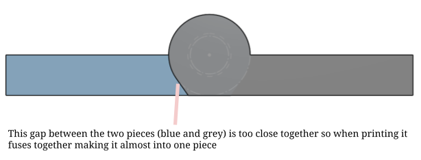
After this I exported the part and moved into AnyCubic Slicer (the slicer that is used to compile the g-code of the part for the 3D Printer). However, after printing the part itself I realized the gaps between the two parts were too small. Because of this, when the printer was creating the print the two pieces fused together making it unable to bend.
Attempt 2
To fix this problem, I decided to roll back the sketch to the original side profile of the hinge. Originally, I had planned on using an offset tool to create the gap between the two pieces. However, after looking at Onshape's offset tool I realized that it could only be used to make a part larger and not smaller, which wouldn't work for this purpose. Instead to change this problem, rather than creating the full part on one sketch, I only created one half of the part. I then extruded it and added the same cone-like shape that would act as a hinge to it.
|
|
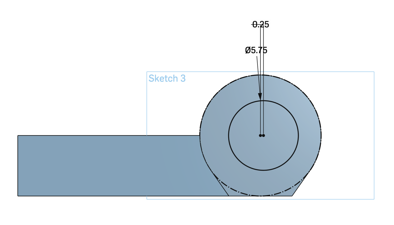
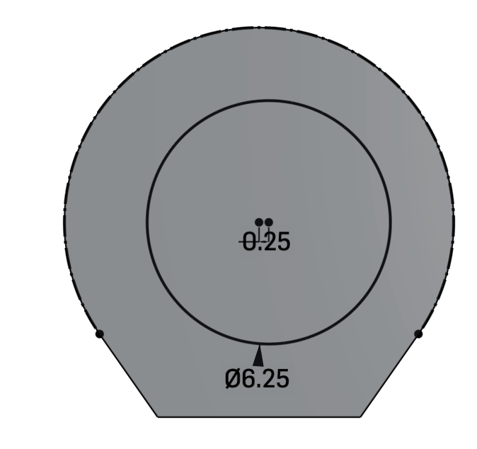
After doing this I created another version of the sketch, and offsetted the piece in the sketch in the sketch itself. While doing this, I made sure that although the barrel was offsetted, the cone-like piece was aligned with the hole on the other piece. To do this, I made it so that the circle that was the base was slightly offcentered so that both would align.
This is how I offsetted the barrel in the sketch itself. In this sketch it is offsetted by 0.5 mm.
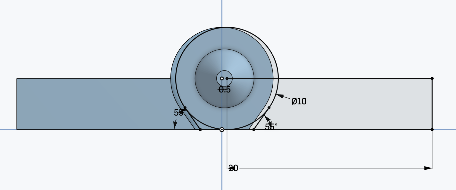
Both of the circles for the cone-like piece are offsetted by 0.25 mm in opposite directions making it so that they have a total offset of 0.5 mm and therefore align with each other.
|
|
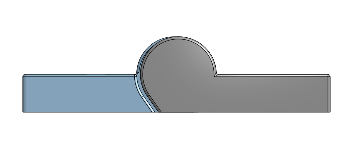
After doing this I created the second piece using the sketch, and then mirrored the part to get a similar hinge piece as I had before. On the previous hinge, I had stopped here and began moving the piece to the slicer. However, for this iteration I decided to fillet the piece so that there weren't as many sharp ends. Additionally, filleting the corners would slightly increase the gap between both pieces. While doing this I also made sure not to fillet edges that would directly touch the print bed, as doing so would weaken the print's base and may cause it to slip while printing the initial layers.
|
|
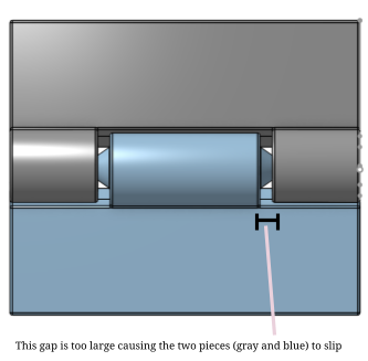
After filletting the piece I once again exported to AnyCubic Slicer and printed the piece once again. However, once printing the piece I realized that the gap between the two pieces was actually too large at the joint itself. Because of this, when moving the hinge the two pieces would occasionally detach from one another, which ruins the purpose of the hinge.
Attempt 3
To adjust this, I decided to make the two barrels of both pieces closer together so that they were less likely to slip. Moreover, I decided to make the cone piece/hole longer and narrower than before, allowing the two pieces to stay together much better than before.
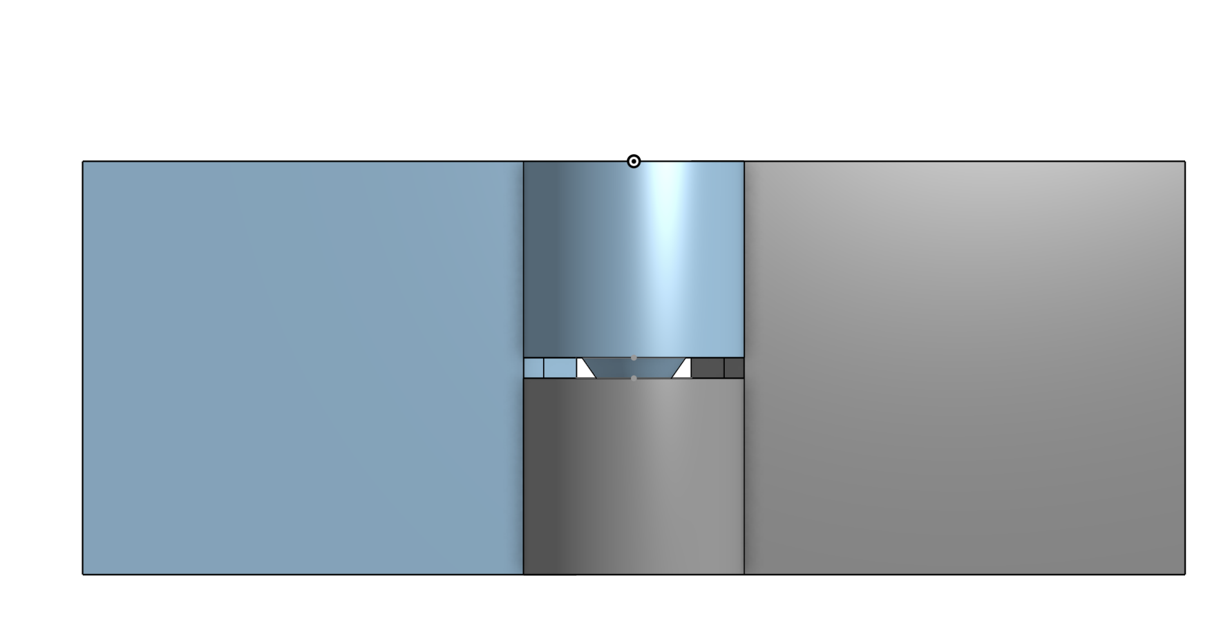
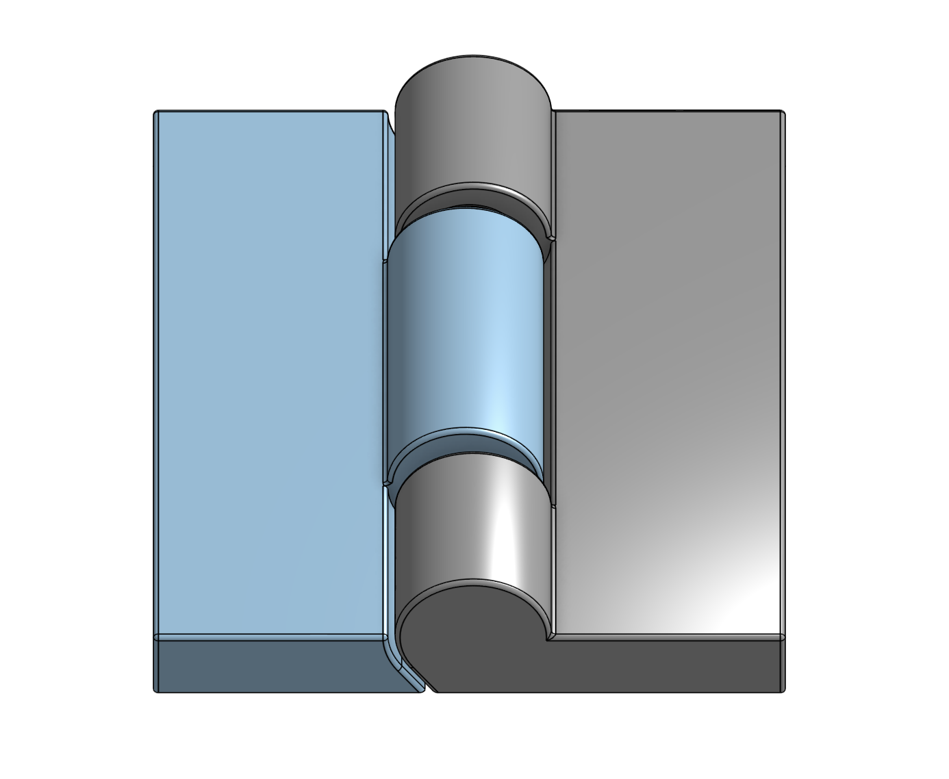
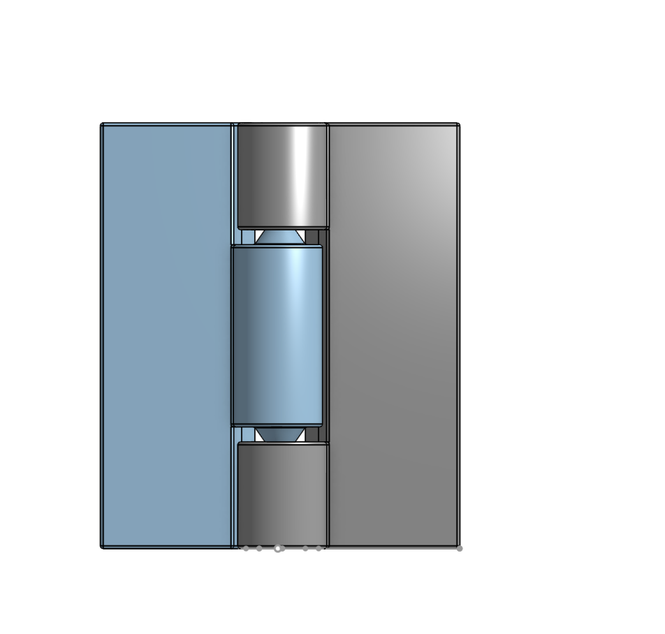
This image is a cross-section view of the hinge from the top. In the "after" image you can see that the cone piece is significantly longer and more embedded into the hole, which is what contributes to the piece's stability.
|
Before (V2) 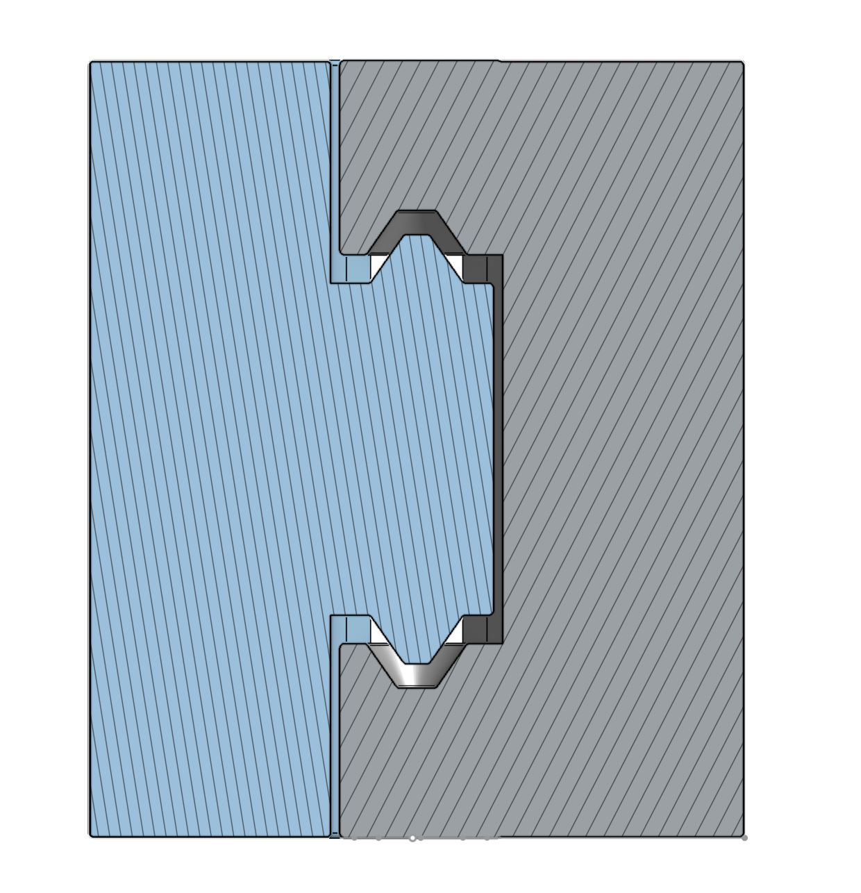
|
After (V3) 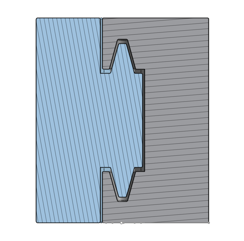
|
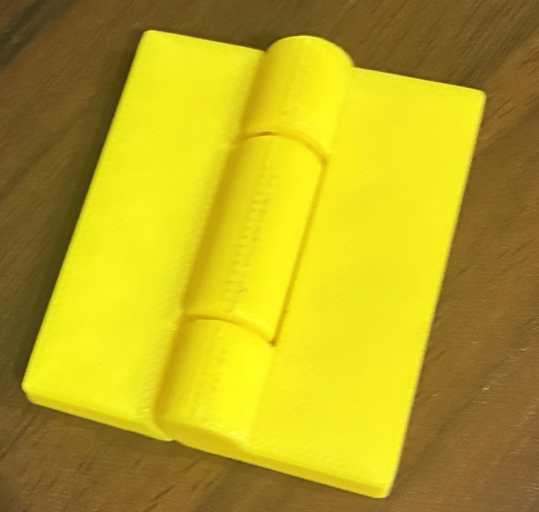
After changing the piece I exported to AnyCubic Slicer and began printing it. This hinge is able to bend and the two pieces are connected and structurally sound.
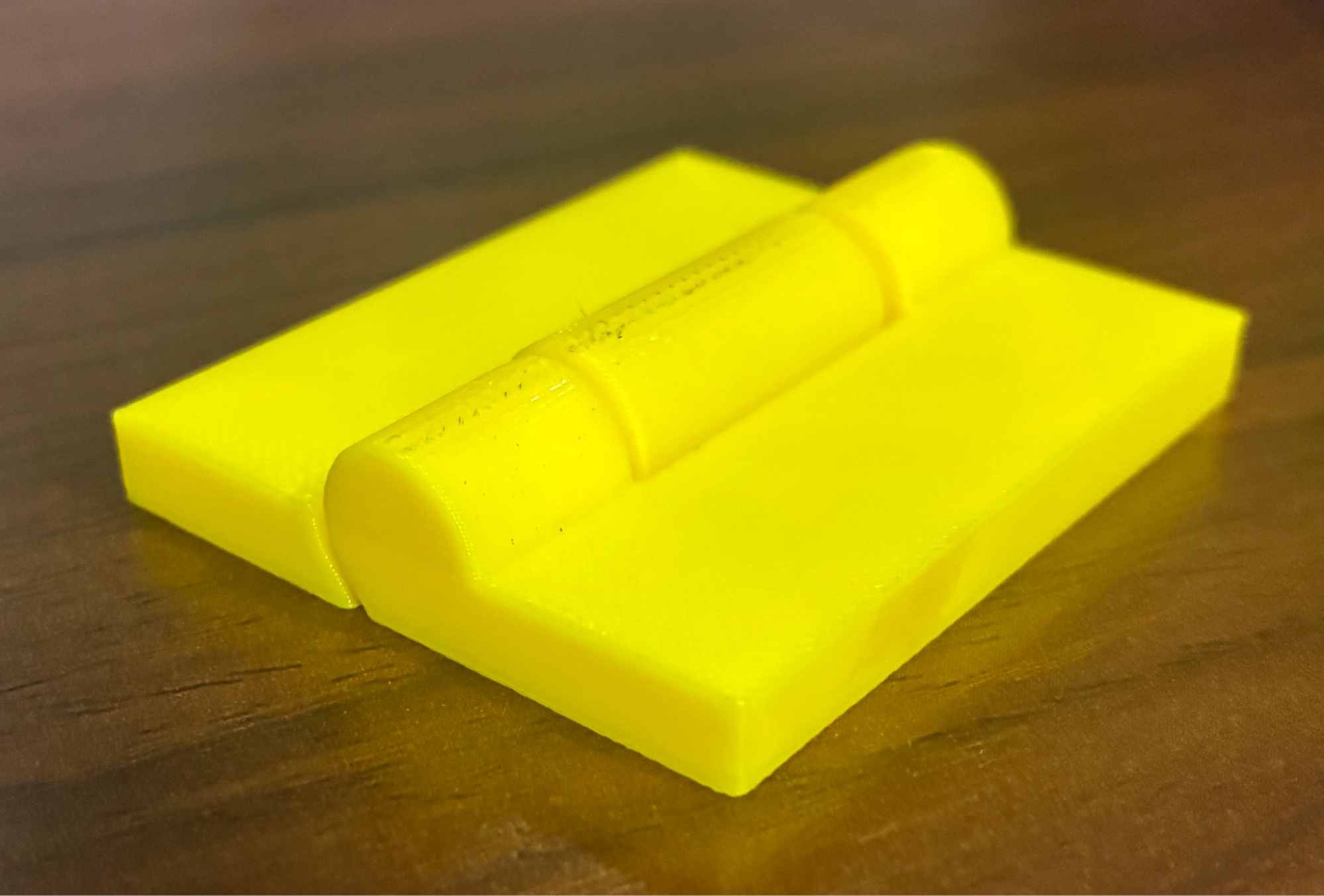
This is how the final hinge turned out:
|
|
|
This is how the hinge looks in its original form (unbent). 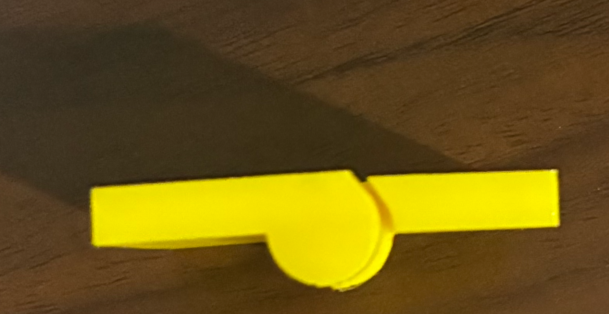
|
This is how the hinge looks when bent. 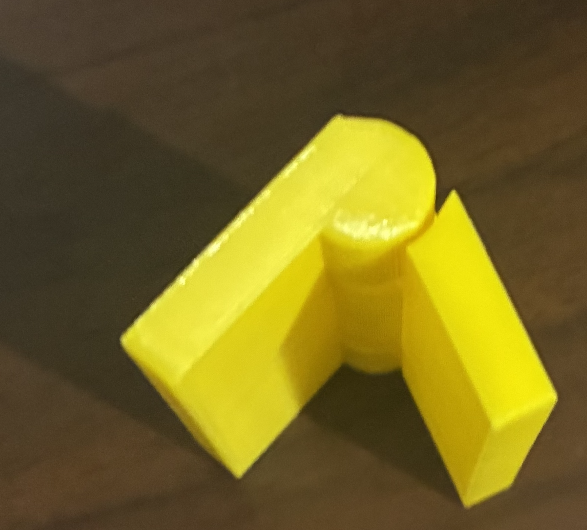
|